
Time: 10 minutes
Analyzer mode: Standby
Wear personal protective equipment.
Use universal precautions.
|
|
||
|
Time: 10 minutes Analyzer mode: Standby |
Wear personal protective equipment. |
|
Put the system in Standby mode.
 Caution
To keep from damaging the probe tip when the power is off, you must manually support the probe and be careful not to strike it against anything on the analyzer.
Cover the cuvettes, wash cups, and other analyzer surfaces with lint free towels to catch any screws that might fall.
Lift and manually rotate the probe to an accessible location, either over the sample tray or over the ISE
Loosen but do not remove the screws on each side of the probe cover, then lift the cover off of the probe arm.
|
|
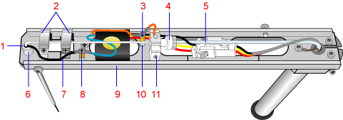
1 Probe (Pipette) 2 Spring Cups 3 Probe Wire Screw 4 Joint Connector 5 Probe Tubing 6 Probe Guide |
7 Black Wire 8 Wire Lock Screw 9 Probe Arm 10 Probe Wire Post 11 Joint Holder (and Locking Screw) |
Using pliers if necessary, gently loosen the probe joint connector (4) and slide it back on the tubing (5) about 1 cm.
Gently flex and pull back on the tubing (5) to remove it from the end of the probe body. Be careful not to damage the flared end or kink the tube.
Loosen but do not remove the locking screw (11).
Loosen but do not remove the probe wire screw (3), then remove the orange probe wire from the post (10).
Securely hold the probe arm (9) and open the two spring clips (2) by grasping each at the side closest to the black wire (7) going to the probe (1) and gently raising each to an open, locked position.
Caution
There is some spring resistance when attempting to open the clips. Do not allow the probe arm to swing side to side when opening the clips.
Loosen but do not remove the wire lock screw (8).
Remove the black wire (7) from the post coming from the probe (1), but leave the blue wire attached.
Gently lift the probe (1) up through the probe guide (6) and carefully remove it from the probe arm (9).
Discard the old probe.
Carefully insert the new probe (1) into the probe guide (6).
Lower the probe fully into the guide so that the rear tube fitting rests in the joint holder(11).
While holding down the the rear tube fitting, tighten the locking screw at the joint holder.
Carefully close each spring clip (2) over the probe.
Caution
Do not allow the clips to snap on the probe shaft, to avoid damaging the probe.
Reconnect the black wire (7) under the wire lock screw (8) and tighten the screw.
To prevent damaging the wire, avoid flexing the wire more than necessary.
Caution
If the screw does not fully tighten, or the standoff spins, tighten the screw on the probe arm base until the standoff no longer spins; otherwise the liquid-level-sensing capability may be adversely affected.
Reconnect the orange probe and preamp wires to the post (10).
Carefully flex the tubing (5) and slip the flared end into the probe joint holder (11).
Slide the knurled nut of the joint connector (4) into the joint holder (11) and carefully tighten until snug.
Caution
To avoid damaging the threads or introducing leaks or air bubbles, do not cross thread or force the joint connector in too far.
Replace the probe arm cover and tighten the two probe cover screws.
Lift up the probe arm (9) to the end of its travel. Manually lift and rotate the probe over the probe wash cup but not within the wash port.
Put the system in Operating mode.
At the Menu Panel, select Maint., then select User Maintenance.
Using the User Maintenance window
At the User Maintenance window, in the Position Probes for Routine Cleaning area, select Start, then select Yes when prompted.
Ensure that the probe is perpendicular to the arm and centered over the cuvette.
If the probe is not centered, call your local technical support provider or distributor.
At the Operation Panel, select Initialize to return the probes back to home (over the wash cups).
At the Operation Panel, select Prime then Prime 2 then Execute to ensure proper water flow through the probe.
Note
Make sure that no water is leaking from the joint connector (4).